1 Working Principle and Main Classification of Reducer
In mechanical transmission systems, a reducer functions as a critical intermediate device connecting the power source and actuator. Its core mechanism involves gear reduction and torque amplification through mechanical transmission. Specifically, the reducer employs a gear system where the input shaft (with fewer teeth) meshes with the output shaft’s larger gear, effectively decelerating the high-speed rotational force of the prime mover while increasing the output torque. As a result, reducers are extensively utilized in low-speed, high-torque transmission equipment and are considered a key factor influencing robotic performance.
Reducers come in diverse types and models to meet the varying power transmission needs across industries. They can be classified in multiple ways. Based on control precision, reducers are categorized into general-purpose reducers and precision reducers. General-purpose reducers offer lower control precision but suffice for basic power transmission in general machinery. Precision reducers, on the other hand, feature high accuracy, extended service life, minimal backlash, and superior reliability, making them ideal for high-precision control applications in industrial robotics, collaborative robotics, industrial automation, and other advanced manufacturing fields.
Precision reducers, primarily RV reducers and harmonic reducers, are core components in high-end equipment manufacturing such as robotics, accounting for approximately 35% of the total cost of an industrial robot. These reducers are widely used in high-precision control applications including industrial robots, collaborative robots, and industrial automation, where they face high technical barriers. Specifically, harmonic reducers are designed for lightweight, low-load applications, while RV reducers are optimized for medium-to-high load scenarios requiring high torque and rigidity. The latter demands more advanced technology, presents greater challenges in production and assembly, and has a lower domestic production rate. Currently, Japan’s Nabtesco maintains a leading position in this global market.
Due to their distinct technical characteristics in transmission principles and structural designs, these two systems demonstrate complementary advantages in downstream products and application domains, serving diverse scenarios and end-use industries. A concrete comparison in industrial robotics is as follows:
project
RV decelerator
harmonic reducer
Transmission principle and deceleration structure
The reducer is composed of the first stage involute planetary transmission and the second stage cycloidal planetary transmission. At least two eccentric shafts are used to connect the second stage reducer. The pinion and cycloidal gear are made of solid castings and steel parts.
The system is composed of three core parts: the flexible wheel, the rigid wheel and the wave generator. It is simple and compact, and the material, volume and weight are lower than the RV reducer.
performance characteristics
Large volume, high load capacity (allowable torque load can reach 28,000 N·m), high stiffness; but at the same time, the product uses relatively complex over-positioning structure, manufacturing process and cost control is more difficult
The volume is small and the load is low (the allowable torque load is up to 1,500 N·m), but the key gear is a flexible element, and its performance is gradually reduced under repeated deformation, and the bearing capacity and life of the product are limited.
load bearing capacity and life
The product can achieve higher product torque and anti-impact ability, torsional overturning stiffness, fatigue strength is greater, precision life is longer, high motion precision.
The flexible gear transmission has low fatigue life and weak torsion resistance.
synovial joint
It is more suitable for large torque and heavy load joints such as robot base, waist and upper arm.
It is generally used for light load positions such as forearm, wrist and hand.
Actual usage
RV reducers are primarily used for loads above 20kg, while RV harmonic reducers are recommended for loads between 6kg and 20kg.
For loads under 6kg, harmonic reducers are typically used.
Main terminal application areas
The field of medium and heavy-duty robots, represented by industries such as automotive, photovoltaic, welding, bending, spraying, palletizing, metal processing, transportation, and port terminals.
The 3C electronics, semiconductor, food, injection molding, mold, and medical industries are in high demand for light-duty robots.
.2 Working Principle and Characteristics of RV Reducer
As defined in GB/T 34897-2017 “Precision Bearings for RV Reducers in Rolling Bearing Industrial Robots”, an RV reducer is a transmission mechanism comprising a planetary gear reducer as the front stage and a cycloidal pinwheel reducer as the rear stage. It features a high transmission ratio and self-locking capability under specific conditions.
The RV reducer, developed from traditional pin-torsion planetary transmission, features a dual-stage reduction system comprising a planetary gear reducer as the front stage and a cycloidal pinwheel reducer as the rear stage, with at least two eccentric shafts connecting the two stages. Its housing and cycloidal pinwheel are solidly coupled through castings and steel components, forming a closed differential gear train. This innovation not only overcomes the limitations of conventional cycloidal pinwheel transmissions but also delivers a range of advantages including high precision (with tooth clearance below 1 arc minute), exceptional rigidity, superior durability, high output density (compact yet powerful), a broad speed reduction ratio, and minimal vibration.
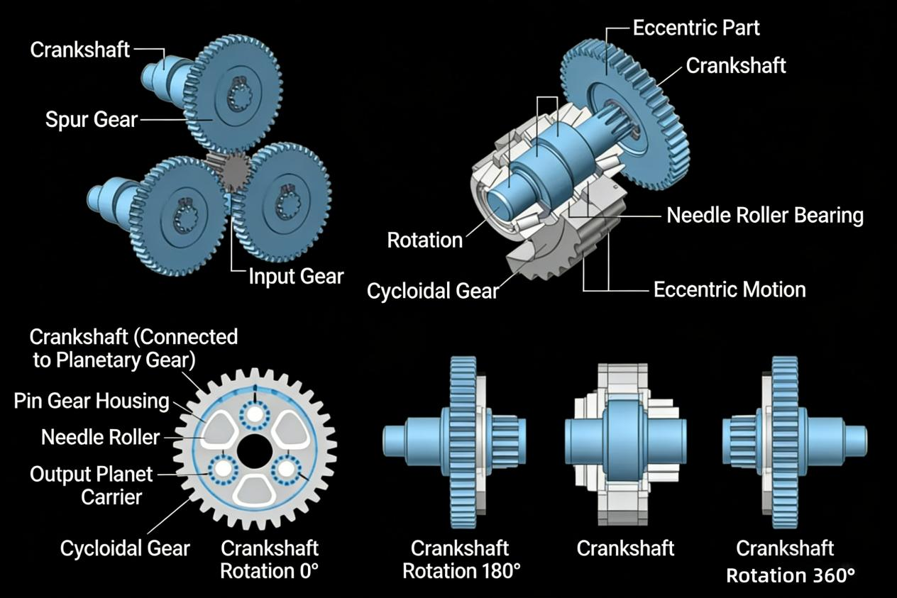
The motion transmission process of the RV reducer operates as follows: The servo motor’s rotation is transmitted to the planetary gears through the input gear. Based on the gear ratio between the input gear and the planetary gears, the speed is correspondingly reduced (first-stage reduction). The crankshaft is directly connected to the planetary gears, maintaining the same rotational speed. Two cycloidal gears are installed between the eccentric section of the crankshaft and the needle roller bearings. When the crankshaft rotates, the cycloidal gears mounted on the eccentric section also perform eccentric motion around the input shaft. On the other hand, the needle roller housing contains needle rollers evenly spaced at intervals, with one additional roller per cycloidal gear. As the crankshaft completes one full rotation, the cycloidal gears engage with the needle rollers while undergoing eccentric motion. During this process, the output planetary carrier rotates one tooth’s distance in the opposite direction to the crankshaft’s rotation. This rotation is then transmitted to the shaft of the second-stage reduction unit (second-stage reduction). The total reduction ratio is the product of the reduction ratios from both first and second stages.